Prerequisites for a neurobotic head device
- Inicio
- Comité Editorial
- Lineamientos
- Carta de Cesión de Derechos
- Información Legal
- Acerca de la Revista
- Bases de Datos
- Contacto
- ISSN 2007-3054
- Centro de Investigaciones Cerebrales
Universidad Veracruzana
José Negrete-Martínez1, 2*, Roberto Cruz-Estrada2, Santiago Negrete-Yankelevich3
1Instituto de Investigaciones Biomédicas, Universidad Nacional Autónoma de México, México D.F. 2Centro de Investigación en Inteligencia Artificial, Universidad Veracruzana, Xalapa, Ver, México. 3División de Ciencias de la Comunicación y Diseño, Universidad Autónoma Metropolitana, Cuajimalpa, México, D.F.
Resumen/Abstract
Introducción
Material y métodos
Resultados
Discusión
Conclusiones
Agradecimientos
Referencias
Correspondencia
Presentamos una cabeza neurobótica, un dispositivo robótico que ha sido instrumentado siguiendo información y principios explícitos (prerrequisitos) para el estudio de neurobiología por síntesis. Los métodos de construcción y pruebas de este dispositivo aplican tales prerrequisitos. El principio directriz es la organización modular en bloques. Los bloques son módulos como: Esqueletal, dispositivos equiparables a Músculos (M-L) y equiparables a Motoneuronas (Mn-L), trenes de pulsos equiparables a los Nerviosos, selectores Mn-L, receptores equiparables a Sensores; y módulos Sensorial e Integrativo. Los elementos de construcción son: ocho servo motores M-L, dos sensores de luz, dos sensores de sonido, un acelerómetro, un microcontrolador y una computadora personal. La cabeza consta de un módulo integrativo visuo-motor programado para producir una conducta compleja autónoma de búsqueda ojo/cuello.
Palabras clave: Cabeza robótica, Vida artificial, Robot neuromórfico, Neurobot, Robot biológicamente inspirado, Teoría neurobiológica.
We present a neurobotic head, a robot device that has been instrumented following explicit principles and data (prerequisites) for the study of neurobiology by synthesis. The methods of construction and tests of this device follow such prerequisites. The main principle is the modular organization in blocks. The blocks are modules as: Skeletal, Muscle-like (M-L) and Motoneuron-like (Mn-L) devices, Nerve-like pulse trains, Mn-L selectors, Sensor-like receptors; and Sensorial and Integrative modules. The hardware comprise of: eight M-L servomotors, two light sensors, two sound sensors, one accelerometer, one microcontroller and one PC. The head has a visuo-motor integrative module programmed to produce autonomous complex eyes/neck seeking behavior..
Key words: Robotic head, Artificial life, Neuromorphic robot, Neurobot, Biological inspired robot, Neurobiological theory.
We define a neurobotic device as an instrument that bonds mechanics, electronics and computation in a robot with Neurobiologic Principles and Data made explicit in every step of the bonding process to provide a heuristic for studying brain function. The aim is “embedding neurobiological principles on a physical platform capable of interacting with the real world, we argue that an intelligent machine should be constrained by the following design principles (and Neurobiology principles): (i) it should incorporate a simulated brain with detailed (modular) neuroanatomy and neural dynamics that controls behavior and shapes memory, (ii) it should organize the unlabeled signals, those which receive from the environment, into categories without a priori knowledge or instruction, (iii) it should have a physical instantiation, which allows for active sensing and autonomous movement in the environment, (iv) it should engage in a task that is initially constrained by minimal set of innate behaviors or reflexes, (v) it should have a means to adapt the device’s behavior, called value systems, when an important environmental event occurs, and (vi) it should allow comparisons with experimental data acquired from animal nervous systems”. From here on the aforementioned statements are Krichmar-Edelman (K-E) principles.1
In this communication, we show how materials, motors, sensors, computer devices and their associated programs can be systematically organized following neurobiological prerequisites into modular units or neuromorphs2 to develop a neurobotic device. We will also show that the device can display behavior that can generate valid neurobiological theoretical considerations.
In ICABB-2010,3 we presented a model that is not a neurobotic device but a computational model that given its nature has been incorporated in the present neurobotic head as an integrative component.
Our device belongs to the low technological complexity and intermediate human likeness in the classification of Berns and Braum.4
2.1. The head construction following neurobiological principles (K-E I, II, III and IV)
2.1.1. Assembling metal hoops as modular-bones
Our robotic head (also named Cranium) has a cranium skeleton constructed in an armillary structure by assembling three orthogonal aluminum hoops (Coronal, Sagittal and Transversal modules) as shows the Figure 1. The structure is supported by a rotating arch supported by two neck-pillars that rest on a horizontal axial ball-bearing (which is fixed on top of a pedestal) and by an upper support. This cranium encloses the sensors and the hardware.
"L-shaped” holders and the facial region of the Transversal hoop compose the orbit cavity. The L-shaped holders are articulated with the Sagittal Hoop and this L-shaped supports the articulation of a globular eyeball camera (webcam) in each “orbit cavity”.
Each eyeball camera has an incorporated Microphone and one accelerometer is attached to the Coronal hoop near its articulation with the Transversal hoop.
A microcontroller and a PC complete the ‘brain’ hardware of the cranium skeleton.
2.1.2. Modules external to the skeleton of the head
The head is equipped with eight servomotors. The motors are also articulating points of the movable parts of the head: there are four servos in the eyes assembly, one servo articulates with each of the two eyeball cameras (horizontal eye movement), another servo articulates with each of the two L-shaped holders (vertical eye movement); and there are four servos to the head movements, a pair for the Sagittal-Transverse hoop articulations (vertical head movement), and another pair for the supporting arch articulations (horizontal head movement). To make sense, articulations for the robot are the shafts of the servos rotating to move a structure. For each shaft the possible movement is either clock or counterclockwise: one degree of freedom (DOF).
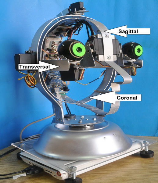
Figure 1. The Skeleton modules (hoops) of the head. The hoops are supported by an arch with pillars standing in a horizontally rotating ball bearing; all above is placed on a top of a pedestal and this is resting on a leveling acrylic plate. Under the plate there is a notebook PC computer. In the inner faces of the sagittal and transversal hoops are located one microcontroller; one ad hoc LIC circuit; and one accelerometer. Webcams are supported through “L” shaped mobile holders by the nasal part of the sagittal hoop.
2.1.3. Eyeball articulation
The two L-shaped holders are moved by one servo each, attached by their vertical blades to the axes of servos fixed in the internal nasal part of the sagittal hoop. These servos through the holders are equivalent to the ‘superior-inferior recti-muscles’. Below each eyeball a servo attached to the horizontal blade of the L-holder is equivalent to the ‘external-internal recti muscles’.
2.1.4. Neck articulation
The shafts of the two servos fastened in the head holder form a virtual horizontal axis of the head. These servos actually are equivalent to the ‘flexors-extensors neck muscles’. They rotate the sagittal hoop and thus the entire head.
A virtual vertical axis of the head runs between the shaft of one servo below the pedestal and another at the top of the auxiliary support pillar. Both servos are equivalent to the ‘head torsion muscles of the neck’.
2.2. Software ‘Brain’ (K-E V): Motor units action-selection and neuron-modulation
PC programs specify which motors should be moved and the modulating function that will drive them through a microprocessor. The microprocessor is programmed to generate a Pulse Width Modulated (PWM) signal, which eventually moves the selected servo motors. This PWM is equivalent to the spike frequency modulated signal that moves the muscles. The difference is that the PWM is constantly acting (‘tonic’ signal) while in animals the spikes fired by the motor-neurons can be bursting signals (‘phasic’ signals). The commands that specify the servo activation in angle and duration are equivalent to the stimulation of synaptic action by step current injection.
Action selection is equivalent to motor unit selection in the Central Nervous System (CNS) and the modulation function is equivalent to the resulting pre-motor neuron activation of the motor modules.
The light, sound and acceleration sensors feed ad-hoc programs written in Processing language that incorporate the sensors into sensorial modules.
2.3. Experimental setup for detailed eyeball or head movements
We designed an experimental setup for the study of the movements. We recorded them with one webcam pointed to an oscilloscope screen. The movement of the oscilloscope light-spot was recorded when its direction was perpendicular to the movement direction of the webcam or when the webcam remained fixed and the head movement direction was perpendicular to the direction of the light-spot movement.
2.4. Sensing observations
Moving or static images from an oscilloscope screen are presented to the eyeball cameras and sound tones from ad-hoc device are auditory stimulus to the present neurobotic head. Manual movements of gravitation accelerations are also applied to the head.
3.1. Visual fields
The visual field images are shown in Figure 2 a), they were taken with a Processing Language program ‘image-capture’ when both cameras were pointing at the same location, and otherwise, the image-capture program takes one webcam field after the other, with a time difference of 30 milliseconds.
3.2. Aural fields
There is a sound sensing asymmetry for each of the microphones when sound amplitude is recorded from a single sound source, as can be seen in Figure 2 b) for one microphone. The source of the sound is changed to different positions, in the same plane and at the same distance. We also found that the webcam microphones do not detect vibration when it is applied directly to the hoops.
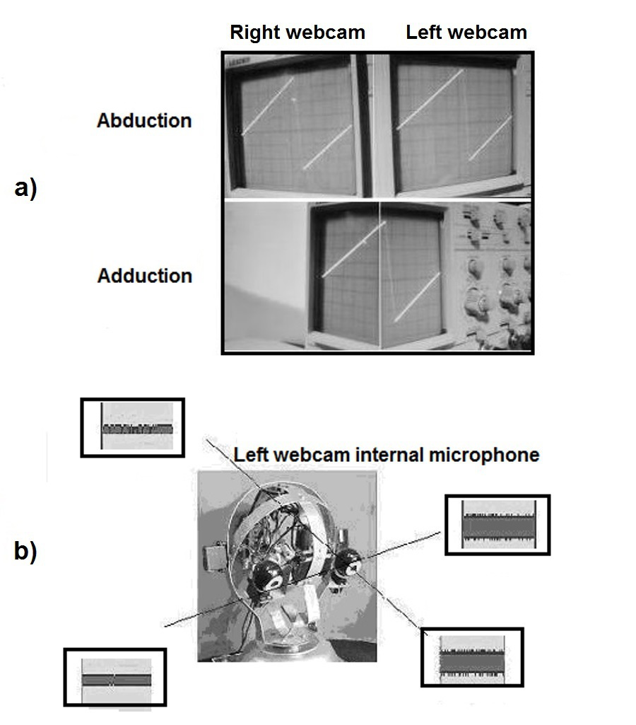
Figure 2. Sensorial response of the head: a) Visual field of the two webcams. b) Aural field of one microphone.
3.3. Vestibular fields
The field of the accelerometer is the gravity field, while a permanent magnet is attached to the pedestal to generate a reference magnetic field.
3.4. Head kinematics
Cranium skeleton is supported by two virtual axes, one vertical and one horizontal. The latter feature reduces the kinematics of the neck5 to two DOFs. The camera holders reduce also the DOFs of the eye6 to only two.
3.5. Head Kinetics
The center of mass of Cranium is ahead of the horizontal axis therefore the resting position of the head is facing down. We use two servos acting simultaneously to minimize the severe over-damping that would otherwise be imposed on a single servo due to this imbalance. The imbalance is similar to that observed in the human head, which is supported in its extension by several anti-gravitational neck muscles.
3.6. Saccadic eyeball movements
When the time-function scanning response of a webcam is controlled by a linear staircase modulation function in which each step height is specified by a write command (1 degree) and duration by a delay command (10 milliseconds), the resulting camera scanning is observed as a ramp function.
When a single servo in the horizontal axis tilts the head, this servo is subject to considerable torque and thus overdampens the movement. However, when the second servo acting on this axis is activated in the same direction, this hindrance is overcome.
Sinusoid modulated staircase signals can be generated producing sinusoidal oscillations of the webcams. Amplitude gain and phase differences of the oscillations can be recorded and plotted against oscillation frequency.
3.7. Visual sensorial recordings
An experiment with a visual sensorial-unit program was performed as shows the Figure 3. The difference in the red color for each pixel between two successive frames was programmed for this experiment. Therefore the image was shown only when the object was moving, otherwise there is no image.
3.8. Aural sensorial recordings
The Figure 4 shows an experiment performed with the auditory sensorial module. The corresponding neuromorph program of this module was presented with a sequence of pure tones running from 10 to 5120 Hz. The tones were passed in the program to a pass-band filter and then to a frequency spectrum generator.
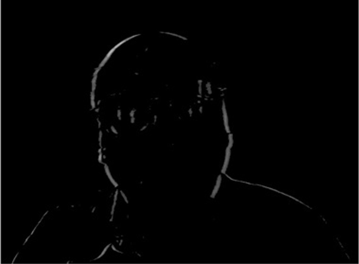
Figure 3. Image taken with a ‘two frames difference program’ when a subject in front of one camera was moving and the threshold of the difference was 10 brightness units.
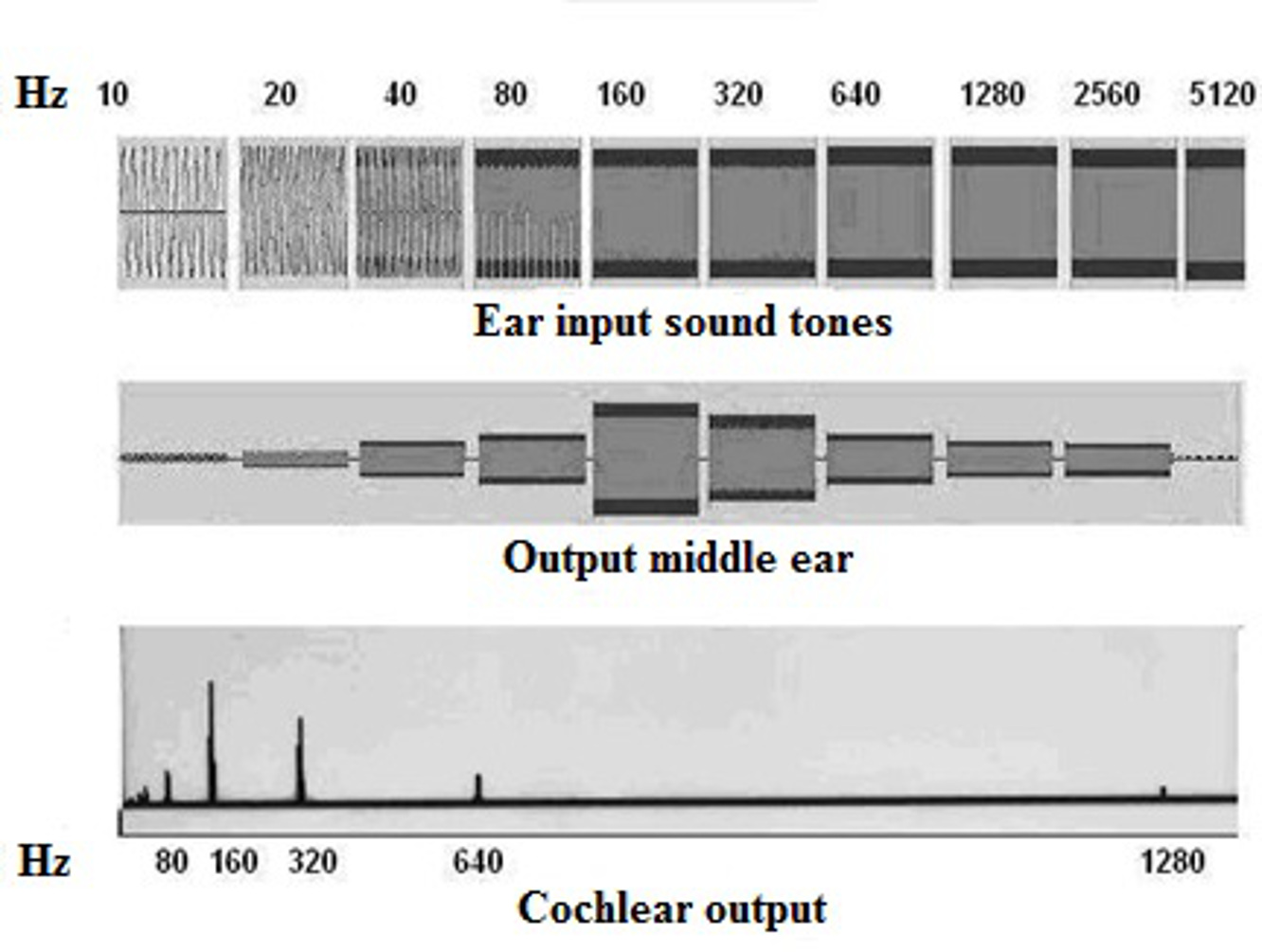
Figure 4. Experiments with Aural sensorial programs. Each row in the image corresponds to the audio processing of a set of single tone stimuli (first row); band pass filtering of the set produced by the middle ear neuromorph program (second row); spectral analysis of the set produced by the cochlear neuromorph program (third row).
3.9. Semi-circular-channel sensorial recordings
The output of the accelerometer is passed to the microcontroller. The PWM output signal produced in the microcontroller is passed, through a Leaky Integrating Circuit (LIC), to an oscilloscope. The accelerometer is programmed for dynamic measurements or for static measurements.
Manual acceleration of the head is recorded in the oscilloscope with the dynamic program as shows the Figure 5a). With the static program the head positions are taken during a free-falling flexion, see Figure 5b).
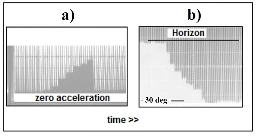
Figure 5. ‘Spike trains’ output selected (note that in both images the spikes are going down): a) The spikes are generated when the head is horizontally moved and manually accelerated to the left. b) The spikes correspond to the detection of the successive positions of the head during its free flexion gravitational falling (utriculus neuromorph).
3.10. Utriculus sensorial recordings
A compass program in the accelerometer sensor captures the static tilt position of the head. This program modulates the PWM in the microcontroller card and thus generates a pulse train proportional to the altitude of the head relative to the permanent magnet described above. The amplitude of the recordings is proportional to the head position when this is tilting-down freely. We notice also small oscillation of the head at the end of the movement as can be seen in Figure 5b).
3.11. Neurobiological behavior
The gazing activity of Cranium, with an Integrative Program is similar to the Superior Colliculus model program of Negrete and Negrete.3
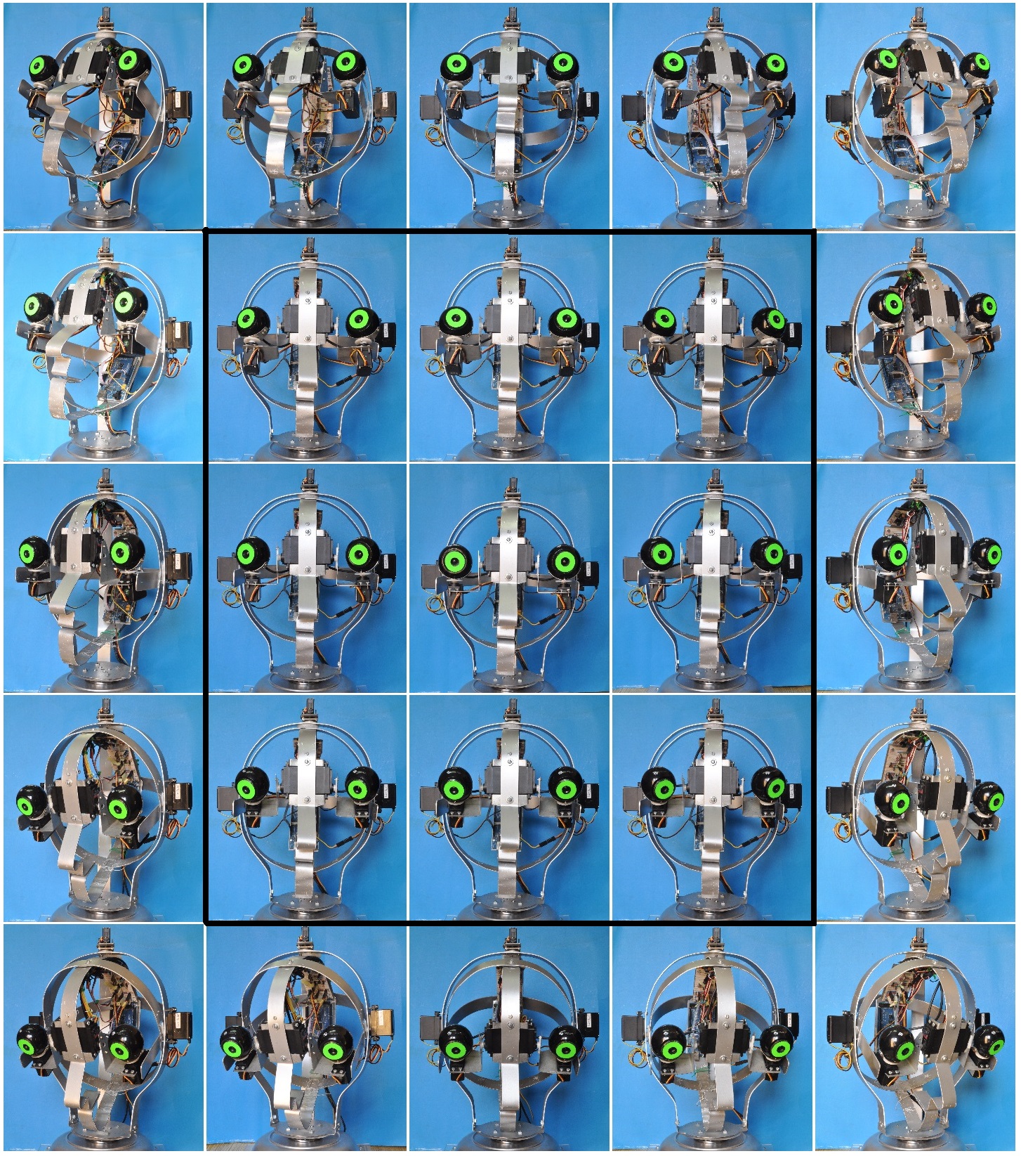
The Figure 6 shows the gazing activity of the device. The gazing in the central visual field is eye-movements only (black 3 X 3 images square), while in the peripheral field the gazing comprises both eyes and head movements.
4.1. Comparative ‘neurobiology’
4.1.2. Kinetics
The kinematics is severely reduced due to the use of axes as articulations. This is equivalent to making use of wheels. The servos, like muscles, are implemented to produce rotational forces instead of pulling forces. The internal feedback mechanism of the servos produces a pillar rigidity effect on their drive shafts that differs from the mechanical and physiological compliance observed in living muscles.
4.1.2. Modules have a neurobiological organization
The modules in Cranium can be organized into four groups: The first group can be divided into eyeball or neck motor modules. The eyeball motor unit can be further divided into abducting and adducting modules. The second is the light sensorial group and can be divided further into cone-oriented and plexus (lateral inhibition) oriented. The third group is a single sound-sensorial type (one per side) and the fourth group of modules can be divided into channel type (sagittal channel and coronal channel; a total of two) and utriculus type. All of these groups are bilateral, with the exception of the fourth group.
4.2. Neurobiological data followed in the present robotic head (K-E VI)
1. The Cranium skeleton is constructed with three inter-assembled metallic hoops. Together, these create a rigid framework to locate sensors and controlling devices in a convenient biological arrangement. The human cranium is a bone case that houses the internal ear, the eyes and most of the brain and cerebellum in a similarly convenient topolography.
2. The “L” shaped holder forms part of the internal face of the Cranium ‘orbits’. However, this internal face is mobile. Its biological counterpart corresponds to the internal bony face of the orbit. The human cranium has two completely separate nternal boxes, the orbital cavities, with the same function as the incomplete and mobile holders in our Cranium.
3. The horizontal and vertical visual angles in Cranium eyeballs are much reduced (60° each one) compared to the corresponding angles in the human eye (>120° horizontal and >40° vertical)7. The frontal position of the eyes is a very important feature for the development of visual survival dependence.
4. An unexpected left-right hearing asymmetry exists in Cranium due to ‘head shadowing’, similar to that found in the human head8, see Figure 2b). This feature adds a binaural difference that is physiological in the detection of sound origin.
5. The microphones program is a sequence of hardware corresponding to the tympanum and middle ear, and completed with a neuromorph program corresponding to the cochlear organ. Sound analysis begins in this initial sensorial organ. See Figure 4.
6. The motor system allows an acceptable capacity of the eyeball webcams to follow constant velocity flying objects. The servos move the globular cameras at a lower speed than the reported slow pursuit movements of the eye9. Active vision depends very much on this feature.
7. Webcam-servo programs could be optimized, generating different activation functions depending on the cranial loads they must move. Eyeball saccades must be programmed in a pulse-step fashion to overcome eyeball inertia.
8. The exocentric mass position in Cranium is managed by two symmetric servomotors functioning in synchrony, as in the synchrony of the muscles of the human head. This issue is directly connected with omnipresent anti-gravitational actions on muscles.
9. Cranium's rotation, on its horizontal axis, is a 1-DOF simplification of a similar movement with many DOF for the flexion of the human head on the cervical column5
10. The eyeball camera movements on their axes also have a 1-DOF simplification of both the superior-inferior rectus muscle actions and the external-medial rectus muscle actions. Unlike in the human eyeball, there are no torsion movements of the cameras6. Torsion is a very important feature in the estimation of near object distances.
11. The time domain movement responses of the whole Cranium are always damped, but to a lesser extent when one axis is moved by two servos synergistically. Muscle unit bilateral redundancy is very important in the human head.
12. We were not able to characterize the frequency response of the eyeball camera as second order, like has been reported for saccades in the living eyeball10. Faster camera-motors should be used in the case where faster saccades are required.
13. The retina webcam program is of sufficient quality to detect light high contrasts or simple movements. The actual retina is a simplified version of the retina cone physiology: transient reactions to differences in light intensity or movement are caused by the indirect cross-inhibition of the signal-transporting bipolar cells in the plexiform layers of the retina11. More sophisticated programs must be implemented where more complex object features must be detected.
14. The frequency analysis of the sound signal perception seems to be satisfactory for the design of simple neuromorphic devices with sound identification and sound spotting.
15. The accelerometer represents a suitable input for future optokinetic reflex implementation in higher stage neuromorphic devices. This reflex allows objects to be followed when the head or the body is in motion.
The neurobotic head device reported here is intended to serve as an aid for learning and discovering in neurobiology through CNS synthesis of neurobots (neuro heuristics).
The physical implementation of our neurobotic device is the consequence of the enaction framework cognitive position principle12 very aptly expressed by Sandini et al.13: “cognitive processes are strongly entwined with the physical structure of the body and its interaction with the environment; Intelligence and mental processes are deeply influenced by the structure of the body, by motor abilities and especially skillful manipulation, by the elastic properties of the muscles, and the morphology of the retina and the sensory system. The physical body and its actions together play as much of a role in cognition as do neural processes”.
Neurobotic devices, including the present head, can be used as heuristic instruments to answer some neurobiological problems. Neurobotic devices are far from biologically inspired devices but rather close to contemporary Artificial Life research14 and Robotics work, an interdisciplinary study of life, of which the two most important qualities are that it focus on the essential rather than contingent features of living systems and its attempt to understand living systems through the artificial synthesis of simple versions of them. Nowadays there are several versions of different technological complexity characteristic of robots in open development projects as the eMorph15 for the iCub13 humanoid robot which is an open source robotic platform available to the community. Finally, according with the cooperative work, we decide also to share with the community our low cost (under $300 USD) neurobotic head device with easy manufacturing parts, easy to buy components and the instructions to reproduce.16
To the Centro de Investigación en Inteligencia Artificial de la Universidad Veracruzana for the scholarship 34369.
There is not any interest conflict with any hardware or software source used (Ubuntu 12.04, Processing and Arduino are Open Source platforms) neither with any university or publishing agency.
- Krichmar JL and Edelman GM. Principles underlying the construction of brain-based devices. University of Bristol. 2006 pp. 37-42.
- Mead C. Neuromorphic electronic systems. Proc IEEE 1990 78:10 1629-36.
- Negrete-Yankelevich S and Negrete-Martínez J. Visuomotor coordination neuromorphic model: gazing expression in robotic heads and cyborg heads. ICABB, Venice, Italy. 2010.
- Berns K and Braun T. Design concept of a human-like robot head. 5th IEEE-RAS ICHR 2005 32- 37.
- Lee SH and Terzopoulos D. Heads up! biomechanical modeling and neuromuscular control of the neck. ACM T Graphic 2006 25:3 1188-1198.
- Bolina O and Monteiro LHA. Kinematics of eye movement. Ophthal Physl Opt 2000 20:1 59-62.
- Howell WH and Fulton JF. Physiology and Biophysics Vol. 1: The brain and neural function. WB Saunders Co, Philadelphia. 1979 pp. 520-521.
- Van Wanrooij MM and Van Opstal AJ. Contribution of head shadow and pinna cues to chronic monaural sound localization. J Neurosci 2004 24:17 4163–4171.
- Buizza A and Schmid R. Velocity characteristics of smooth pursuit eye movements to different patterns of target motion. Exp Brain Res 1986 63:2 395-401.
- Zuber BL, Semmlow JL, Stark L. Frequency characteristics of the saccadic eye movement. Biophys J 1968 8:11 1288–1298.
- Werblin FS. Control of retinal sensitivity. II. Lateral interactions at the outer plexiform layer. J Gen Physiol 1974: 63 62–87.
- Varela FJ. Whence perceptual meaning? A cartography of current ideas. Understanding origins: Contemporary views on the origin of life, mind and society. Boston studies in the philosophy of science. Kluwer Academic Publishers, Dordrecht. 1992 pp. 235–263.
- Sandini G, Metta G, Vernon D. The iCub cognitive humanoid robot: An open-system research platform for enactive cognition. 50 Years of AI. Springer-Verlag Berlin Heidelberg. 2007 LNAI 4850, pp. 359–370.
- Bedau MA. Artificial life. Handbook of the philosophy of biology. Elsevier, Amsterdam. 2007 pp. 585-603.
- Bartolozzi C, Clercq C, Mandloi N, Rea F, Indiveri G, Fasnacht D, Metta G, Hofstätter M, Benosmane R. eMorph: Towards neuromorphic robotic vision. Procedia Computer Science 2011 7 163-165.
- Bartolozzi C, Clercq C, Mandloi N, Rea F, Indiveri G, Fasnacht D, Metta G, Hofstätter M, Benosmane R. eMorph: Towards neuromorphic robotic vision. Procedia Computer Science 2011 7 163-165.Negrete-Martinez J and Cruz-Estrada R. Curso-taller para la construcción y manipulación de una cabeza robótica armillar. Centro de Investigación en Inteligencia Artificial, U.V. 2014. Available on:http://www.uv.mx/personal/jnegrete/files/2014/09/Curso-Taller-Construccion-Craneum.pdf
| Recibido: 05 de marzo de 2015 | Aceptado: 02 de junio de 2015 |
Centro de Investigación en Inteligencia Artificial, Universidad Veracruzana, Sebastián Camacho No. 5, Col. Centro, Xalapa, Veracruz, México, C.P. 91000. Phone: +52-228-8421700 Ext. 12764 and +52-228-8172957 Fax: +52-228-8172855. e-mail: jnegrete@uv.mx
Este es un artículo de libre acceso distribuido bajo los términos de la licencia de Creative Commons, (http://creativecommons.org/licenses/by-nc/3.0), que permite el uso no comercial, distribución y reproducción en algún medio, siempre que la obra original sea debidamente citada.