Functional modularization of a Neurocranium: a robotic brain for a robotic body
- Inicio
- Comité Editorial
- Lineamientos
- Carta de Cesión de Derechos
- Información Legal
- Acerca de la Revista
- Bases de Datos
- Contacto
- ISSN 2007-3054
- Centro de Investigaciones Cerebrales
Universidad Veracruzana
Negrete-Martínez José1,2*, Cruz-Estrada Roberto2, Negrete-Yankelevich Santiago3
1Instituto de Investigaciones Biomédicas, Universidad Nacional Autónoma de México, Cd. de México. 2Centro de Investigación en Inteligencia Artificial, Universidad Veracruzana, Xalapa, Ver, México. 3División de Ciencias de la Comunicación y Diseño, Universidad Autónoma Metropolitana, Cuajimalpa, Cd. de México.
Abstract/Resumen
Introducción
Material y métodos
Resultados
Discusión
Conclusiones
Agradecimientos
Referencias
Correspondencia
We have designed and constructed a modular neurocranium with functional modules from skeleton modules, motor modules, pre-motor modules, sensorial modules, and even integrative modules. We will show that the superior modules, the integrative ones, are determined by the nature of their precedent sensorial and motor modules, and that these last ones, in turn, are determined by the skeleton modules in a true modular functional cascade that reinforces the philosophical position that there is a specific brain for each body.
Key words: Robotic head, Functional modularity, Neurocranium, Neuromorphism.
Hemos diseñado y construido un neurocráneo modular con módulos funcionales que van desde módulos esqueléticos, módulos motores, módulos pre-motores, módulos sensoriales y hasta módulos de integración. Mostraremos que los módulos superiores, los de integración, están determinados por la naturaleza de sus precedentes los módulos sensoriales y motores, y que estos últimos, a su vez, están determinados por los módulos esqueléticos en una verdadera cascada modular funcional que refuerza la posición filosófica de que hay un cerebro específico para cada cuerpo.
Palabras clave: Robotic head, Functional modularity, Neurocranium, Neuromorphism.
The robotic head presented in this paper is a functional modular1 neuromorphic neurocranium which is an extension of a previous paper appeared in this publication.2 The present work fulfills the prerequisites of a robot to be considered a brain based devise3 but in addition it has a modular conception. The morph term has the same sense of neuro-morph invented by Mead,4 but extended to include the skeleton and its functional modularity,5 being a scheme of life organization. Additionally the present contribution belongs to the subject matter of skeleton robots,6 but our work’s aim is not on the field of anatomy physiology and its related behavior, but to support of the philosophical position that there is a brain for a body.7
We started with a design part in which we subdivided the design in four large functional modules: the neurocranium proper (NP); two eyeball (EB), two EB camera-supports (EBCS) and the general support (GS) of whole structure. A second part was the physical rendering of the mentioned design, including the articulation of the large modules: two EBCS with the NP and the NP with the GS, and finally the EB articulation in each EBCS. On the other hand, the EBs are moved by the torsion of servomotor shafts. The rest of the joints are moved by pulling strings through blades fastened to the servomotor shafts. In the case of the strings, they carry springs that constantly pull their corresponding modules with paired forces when there is instability. Regarding each EB webcam, as a light sensor, they were provided with an EBCS. In a third part we constructed four neuromorphs:
A) A PC programed to capture frames focused on the webcam sensors. This neuromorph stores the images in a numerical array in the PC memory.
B) A second neuromorphic module was a servomotor-activation program resident in a microcontroller.
C) A third neuromorphic module was an action-selection program resident in the PC. This program commands the motor activation program.
D) A sensory-motor coordination and integrative neuromorph module was programmed in the PC. The stored frames differences in this module decide the motor actions to be taken.
2.1. Implementation
The construction of this robotic head is preceded by its design, as depicted in figure 1. The names of the modules and their functions are presented in table 1.
Figure 1 shows, in the front view of the neurocranium (NC), two elliptic shapes. The inner one forms part of the cranium while the outer elliptic shape is the edge of the supporting metallic hoop. The elliptic shape in the lateral view is the profile edge of the cranium metallic hoop. The circular shape in the upper view is the metallic edge of the cranium hoop. The rectangles in the different views are the flat surfaces of the aforementioned NC hoops and these are joined together orthogonally.
In the front view of figure 1, the inner cranium ellipse can pivot on a horizontal axis on the outer ellipse, which acts as support for the cranium (articulation depicted with horizontal arrows). This support is also attached to a pedestal and can thus pivot on a vertical axis (depicted in the lower part with the vertical arrow pointing upwards).
The lower right quadrant of figure 1 shows the orbit detail of the squared contour shown in the frontal view. The detail shows a ring pivoting inside the frame and an EB structure that pivots inside the ring.8,9
The arrows in the upper lateral view of figure 1 denote the ‘Sternocleidomastoid’ upper insertion and force direction, and on the right hand side of this view, the ‘Splenius’ insertion and force direction. The Recti force direction in the EB holding ring is shown with arrows in the orbit detail of figure 1.
In figure 1, the main modules are coded in colors according to table 1: the NC set in white, apart from the temporal module, which is in blue. The vertebral and orbital sets are colored in yellow and gray, respectively.
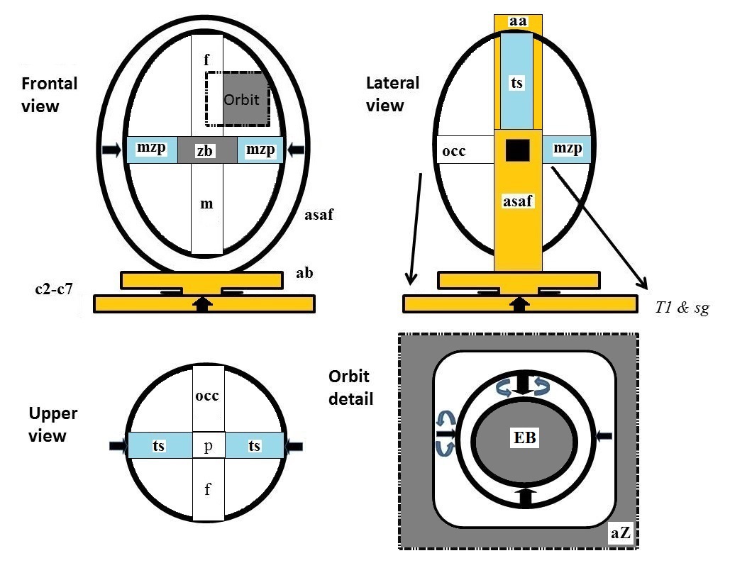
Figure 1. Frontal, lateral and upper views of the modular neurocranium design. In the lower right quadrant of the figure, an amplification of the detail of the orbital region is presented within a gray dotted square contour in the frontal view.
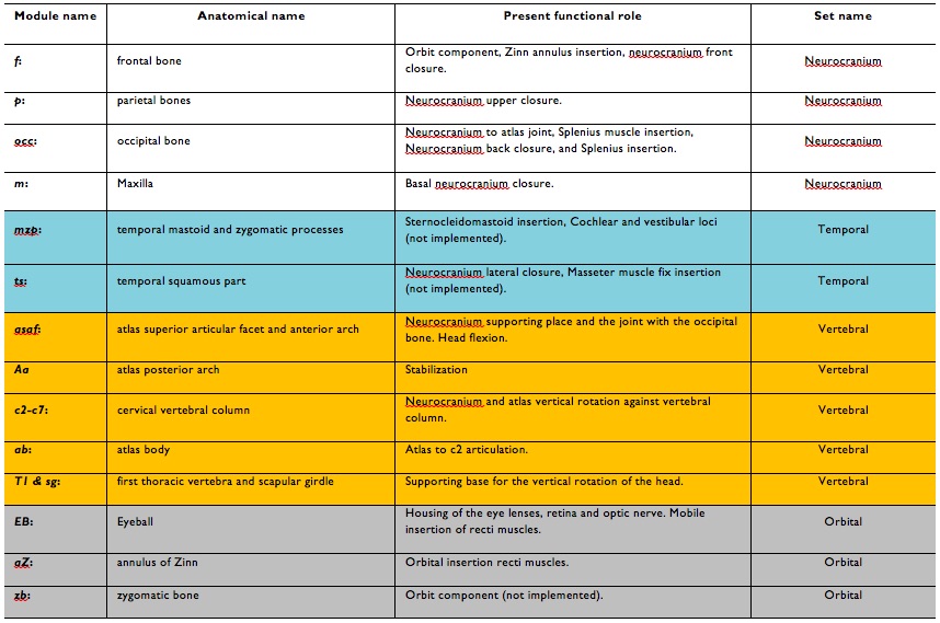
Table 1. Anatomical parts of the head as modules. The background neurocranium module is detailed in white, the temporal module in blue, cervical column in yellow and the orbital module in gray.
2.2. The physical rendering
Figure 2 shows the present implementation of the NC. The equivalent Zinn insertion of the external EB rectus is shown enclosed in a white line square. The mastoid zygomatic processes of the temporal bone module with the upper-end insertion of the sternocleidomastoid muscle module can be seen near to the lower left corner. The white arrow denotes the direction of the virtual horizontal axis of the NC set of modules.
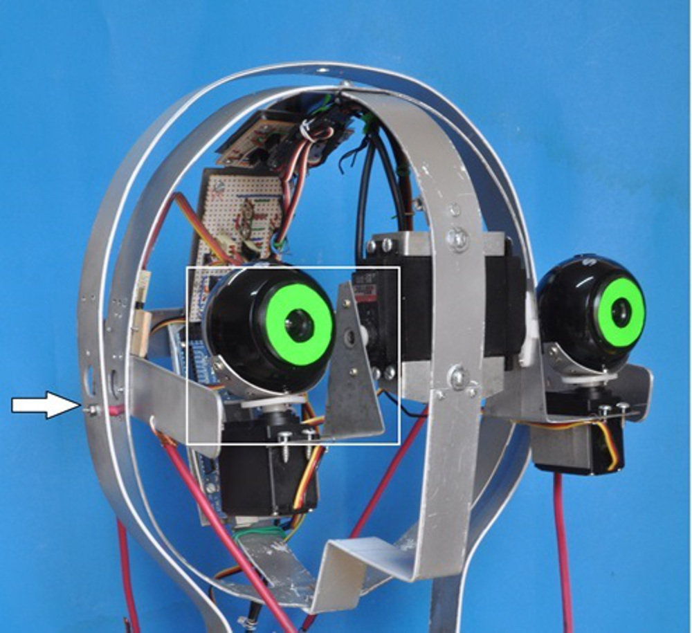
Figure 2. Implementation of the NC. The Zinn insertion band can be seen inside the white line square. The upper insertion of the sternocleidomastoid can be seen in the mastoid process region of the temporal bone. The splenius muscle insertion in the occipital bone is to the rear.
Figure 3 shows, in the lower right corner, the servos that form part of the sternocleidomastoid module, the figure shows also the insertion of this module in the scapular girdle module and the pulling cords inserted in the temporal mastoid process region. The figure also shows the splenium muscle servo at the back of the scapular girdle with its pulling cord inserted in the occipital module.
The complete system includes two more sets of modules logged into the NC: one visual, as a microcomputer programmed to capture and process the frames coming from the EB webcams and the other, a neuromotor set of modules as a microcontroller card for the servomotors.
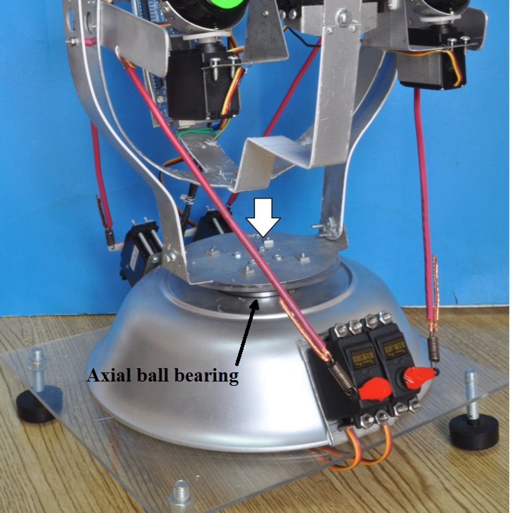
Figure 3. Implementation of the vertebral support of the NC. The atlas body module is on the upper cup of an axial ball bearing and the lower cup forms part of the scapular girdle module.
2.3. The Computer programs
The EB cameras were connected to the USB ports of a microcomputer and programmed for image capture. Programs for the EB movements in the microcontroller consist of sequences of commands directed to another USB port (in order to specify a servo movement), containing the command for each new angular position of the selected servo and the time period for which to remain in that position before the next command. It is a programmed staircase time function.
The programs for the head movements in the microcontroller can be summarized as: a) digital square wave functions, and b) a slow-ascending digital staircase time-function (SASF) in one servo and a slow-descending digital staircase time function (SDSF) in antagonistic servos. Each step is one degree (deg) in amplitude and fifteen milliseconds (ms) in duration. This sequence stops when the staircase reaches angular movements of +60 or -60 deg.
When two servos are pulling synergistically; two SDSF are alternatively built, step-by-step, with a 15 ms phase time-delay between staircases. For the other two driving motors, two SASF are alternatively built up in the same alternating pattern.
2.4. The Recording setup
We performed an experiment with the head and light spot movements, which were recorded from the microcomputer capture programs. The capture program was taken from a Processing library (Processing is an Open Source programming language).10
We captured a 30 deg solid angle visual field as shown in figure 4 (taken from eNeurobiología 2015 6(12):020615).2
Two kinds of experiments were performed with the NC, both directed to demonstrate kinetic aspects,11 of the EBs and entire head. Both required programming of the microcontroller to move the servos, capture the images of the oscilloscope spot and to program the sweeping movements.
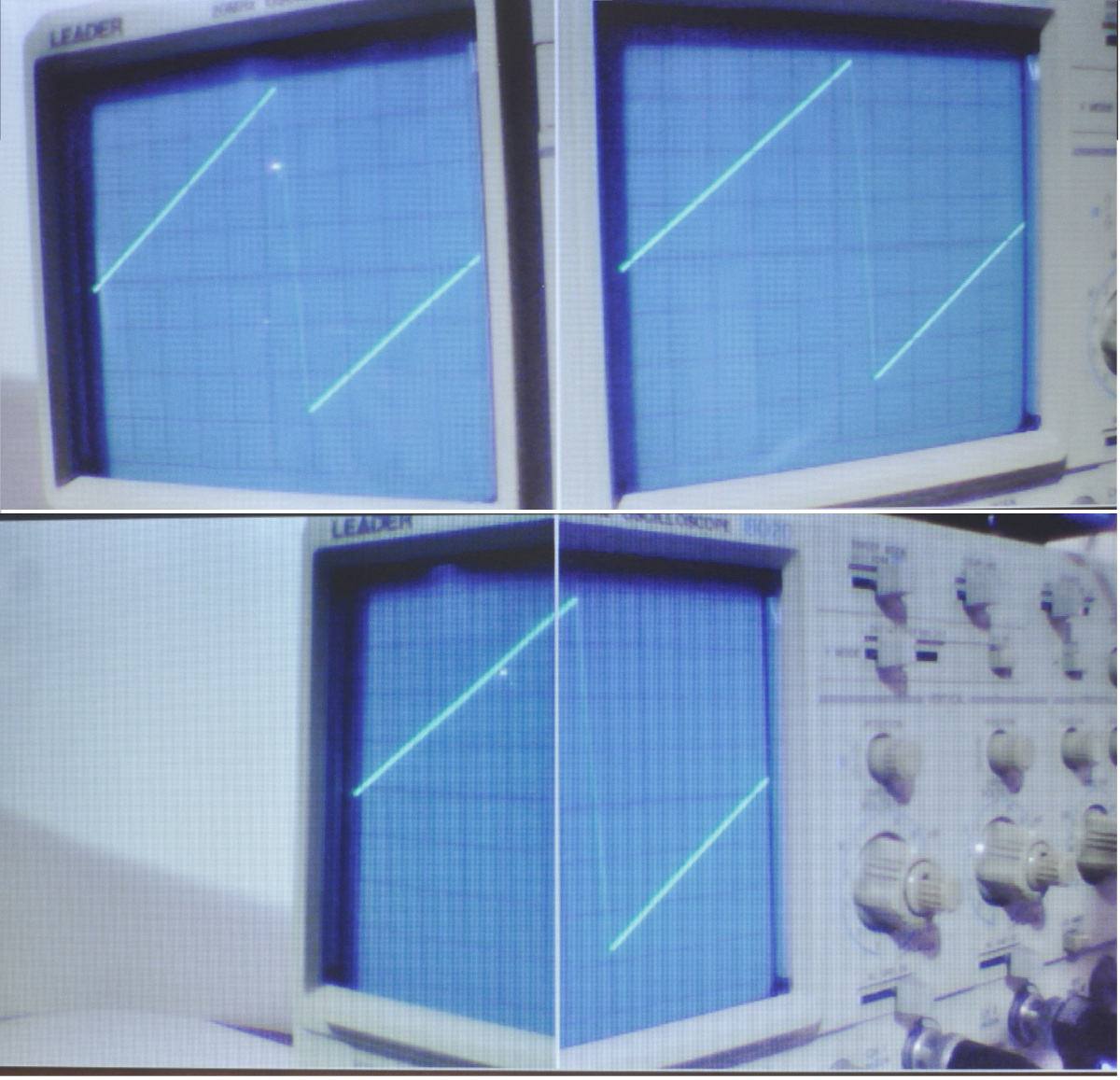
Figure 4. EB cameras visual fields. Each of the two EB cameras is capturing the same oscilloscope screen, but pointing in a divergent horizontal angle (the upper images) or in a convergent angle (the lower image).
3.1. Kinetics and kinematics
The active kinetics of each EB is controlled by the microcontroller and can produce abrupt jerky movements. Similarly, the complete head can be activated in order to produce less abrupt movements (Figure 5). The abruptness is a function of the commanded step amplitude and the mechanical conditions of the servo actions.
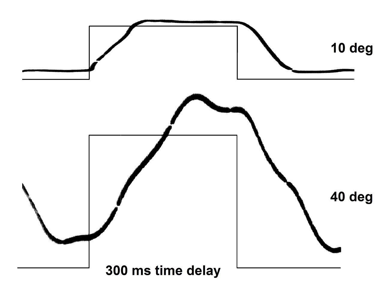
Figure 5. The upper trace is the recording of an EB jerk produced with a ‘digital square wave’ (represented by the superimposed thin line): a sequence of commands of position 85 +10 deg and 300 ms delay followed by a step down from position 95 -10 deg and 300 ms delay. The image (gross line) is the trace of an oscilloscope light spot moving across a screen. The lower trace corresponds to the head movement activated by the splenius module with a sequence of commands of position 70 + 40 deg and 300 ms delay and a step down from position 110 -40 deg.
The head movements recorded in the lower plot of figure 5 was taken when the capturing webcam was immobilized in the orbit of the NC and when the whole head was moving while the oscilloscope spot was sweeping horizontally in the center of the screen.
3.2. Active NC motion patterns
Figure 6 shows the apparent movements of the, otherwise still, image of the oscilloscope spot while a sequence of ‘digital staircase’ servo commands are executed in the microcontroller. The beginning of the sequence is the still position of the spot shown in the figure with a circle.
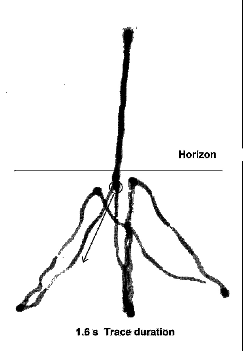
Figure 6. Oscilloscope spot apparent movement captured when the NC executes a sequence of wide movements generated by the ‘neck-muscles’. The starting position is tagged with a small circle and the arrow indicates the beginning of the sequence of movements.
4.1. The functional role implicit in the modularization: “a functionality for each bone”
Thirteen bone modules have been considered in the construction of the NC. Eight muscular motors are inserted into the corresponding modules so they can perform their particular kinetics. The NC functions as the assemblage of a box for a ‘brain’. This box has two orbital windows and two auditory windows (still to be designed). In this box occur the EBs movements (pivoting in the aZ modules). The design of the box demands a neck support with at least two joints to help the sensorial exploration of the EBs.
4.2. Kinetics
The vertebral column has a one-degree of freedom (DOF) joint formed by the atlas bone vertical pillar (asaf) and the occipital blade (occ) (Figure 1). The first thoracic module of the scapular girdle-set of modules forms one DOF joint with the atlas body through an axial ball bearing (Figure 3). All of the modules are modular-functional as box components, mechanical joint supports, stabilizers or regions of muscular insertion.
4.3. Improvements to the kinetics
The EB has two DOF (a simplification of the kinetics) but can be improved with the addition of one more DOF in the Zinn annulus movements with the addition of pulling motors. Improvement of head execution has been achieved without violating the functional-modular principle adopted.3
4.4. The first neuromorphic central nervous system (NCNS) module
The time kinetics with the ‘square wave’ programs very much resemble saccadic movements in the sense that, in order to reach any aiming position in the eye field or in the orientation of the head, they must follow a time function step activation. In the same sense, the microcontroller is an upper motor neuron (the ‘step-function’ program) and a lower motor neuron (the pulse-width modulation (PWM) microcontroller generator).12
4.5. Motor pattern generated by the first NCNS module
Figure 6 presents a continuous recording of an automatic pattern of ‘slow staircase’ commands programmed for deactivation by a programmed switch. The effect of this program very much resembles the spontaneous activity generated by the subthalamic nucleus in the parkinsonians and the switching-off of this activity by electrical or mediator supply.13
4.6. The guidance role of modules in a developing robotic brain
Our first NCNS module is a good example to support the argument that there is a NCNS module for a body: the neurocranium first brain, conditioned by the nature of its construction. Any improvement to the neurocranium will be followed by a new NCNS in order to maintain its functionality. Once any new NCNS module is implemented, a sensorial modular development should be expected in order to ‘conquer’ the behavioral realm, as was the case in Buizza A. and Schmid R.14 In this sense, we can talk of the modular incremental development of a robot.
If there is no new-brain adaptation to any new module addition, we will find that, in building a brain for a pre-existing robot, the brand new brain7 (sometimes a big computer) will have to answer: ‘what is it like to be…?15 a robot, in our cas.
All of the implemented modules have a neurobiological function: encasing, support, joint integration and mechanical force distribution. The encasing of a programmed microcontroller as an initial NCNS module produces a second order functionality in terms of motor coordination. Further, a second order functionality is expected to be implemented as a consequence of the sensorial second order functionality. This developmental process can jump to a third order functionality by integrating several of the second order type: the visuomotor coordination is an example. Finally, the higher-order functionality represents the creation of a behavioral functionality.
Opportunistic functionality is also present, i.e. where we can take the webcam and its program as the beginning of a visual sensorial functionality.16,17 Another opportunistic functionality is the development of a visuo-coordinating neuromorphic module.2,18
We consider that there are enough philosophical,5 neurobiological and practical reasons to expand robotics under the biologic modular-functional principle followed in this work.Finally, the notion of “weak modularity”19 is relevant: “Even though networks compute input-output mappings, the same network may belong to several processing systems; and, while there is a good measure of localization in the brain, it is also often the case that neurons participating in the same computation belong to different regions”. See the same argument in ‘The shape of life’.5 Besides these philosophical arguments, there are strong neurobiological and practical reasons16 to expand robotics under the biological modular-functional principle followed in this work. However, we must be aware that the robotic body including the NCNS is determined by the nature of the mechanical and electronic devices available and the brain for this NC is determined by the nature of the robotic body including its NCNS. But even with this limitation we still have a brain for this body.
This work has been conducted with the support of Centro de Investigación en Inteligencia Artificial de la Universidad Veracruzana, grant number 34369.
7. Conflict of interest
The authors declare that there is no conflict of interests regarding the publication of this paper.
- Functional decomposition, (n. d.).Wikipedia. http://en.wikipedia.org/wiki/Functional_decomposition.
- Negrete-Martínez J, Cruz-Estrada R, and Negrete-Yankelevich S. Prerequisites for a neurobotic head device. Revista eNeurobiología. 2015 6(12):020615. Available on:http://www.uv.mx/eneurobiologia/vols/2015/12/Negrete/Negrete6%2812%29020615.pdf
- Krichmar JL and Edelman GM. Principles Underlying the Construction of Brain-Based Devices. University of Bristol. 2006 pp 37-42.Mead C. Neuromorphic electronic systems. Proc IEEE 1990 78:10 1629-36.
- Raff RA. Why modular Philosophical reason. The shape of life. Chicago University Press, Chicago. 1996 pp 326.
- Potkonjak V, Svetozarevic B, Jovanovic K, Holland O. The puller-follower control of compliant and noncompliant antagonistic tendon drives in robotic system, Int J Adv Robot Syst 2012 8: 143-155.
- Brooks, RA, Stein, LA. Building Brains for Bodies. Auton Robot 1994 1: 7-25.
- Shibata T, Vijayakumar S, Conradt J, Schaal S. Biomimetic oculomotor control. Adapt Behav 2001 9: 3-4 189–207.
- Biamino D, Cannata G, Maggiali M, Piazza A. MAC-EYE: a tendon driven fully embedded robot eye. 5th IEEE-RAS ICHR 2005 62-67.
- Processing library: http://www.processing.org/
- Bolina O, Monteiro LHA. Kinematics of eye movement. Ophthal Physl Opt 2000 20:1 59-62.
- Sherwood L. Human Physiology: From Cells to Systems. CENGAGE Learning 2013; 134-184.
- Bevan MD, Magill PJ, Terman D, Bolam JP, Wilson CJ. Move to the rhythm: oscillations in the subthalamic nucleus-external globus pallidus network. Trends Neurosci 2002 25: 10 525–531.
- Buizza A and Schmid R. Velocity characteristics of smooth pursuit eye movements to different patterns of target motion. Exp Brain Res 1986; 63:2 395-401.
- Nagel T. What is it like to be a bat? Philos Rev 1974 83: 4 435-450.
- Sandini G, Metta G. Retina-like sensors: motivations, technology and applications. In: Sensors and Sensing in Biology and Engineering. Springer Verlag, New York 2002; 251-262.
- Werblin FS. Control of retinal sensitivity. II. Lateral interactions at the outer plexiform layer. J Gen Physiol 1974 63:1 62–87.
- Negrete-Yankelevich S and Negrete-Martínez J. Visuomotor coordination neuromorphic model: gazing expression in robotic heads and cyborg heads. ICABB, Venice, Italy. 2010.
- Kosslyn SM and Koenig O. Wet Mind: The New Cognitive Neuroscience. The Free Press, New York 1992 pp 44-46.
| Recibido: 10 de agosto de 2016 | Aceptado: 05 de mayo de 2016 |
Correspondencia: Negrete-Martínez José Ph. D. Centro de Investigación en Inteligencia Artificial, Universidad Veracruzana, Sebastián Camacho No. 5, Colonia Centro, Xalapa, Veracruz, México, C.P. 91000. Phone: +52-228-8421700 Ext. 12764 and +52-228-8172957 Fax: +52-228-8172855. E-mail: jnegrete@uv.mx
Este es un artículo de libre acceso distribuido bajo los términos de la licencia de Creative Commons, (http://creativecommons.org/licenses/by-nc/3.0), que permite el uso no comercial, distribución y reproducción en algún medio, siempre que la obra original sea debidamente citada.